Embedded System · 2024
Reflow Oven Controller
An oven controller designed for PCB solder reflow, using programmable heating profiles and real-time LCD temperature monitoring.
1.Introduction
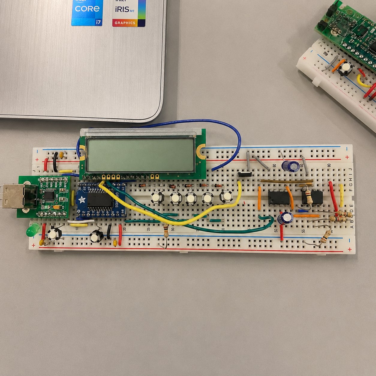
This project is to design a reflow oven controller utilizing the N76E003 microcontroller. The device would enable a standard oven to perform reflow soldering by varying the temperature. This controller will facilitate reflow soldering in a standard oven by regulating temperature, with a target range of 25 to 240°C. It features a user interface allowing the selection of reflow profile parameters such as soak temperature, soak time, reflow temperature, and reflow time. An LCD is attached, and it displays the selected parameter as well as showing temperature, running time, and current status during the reflow process. An emergency stop button is incorporated for unexpected situations.
2.System Design
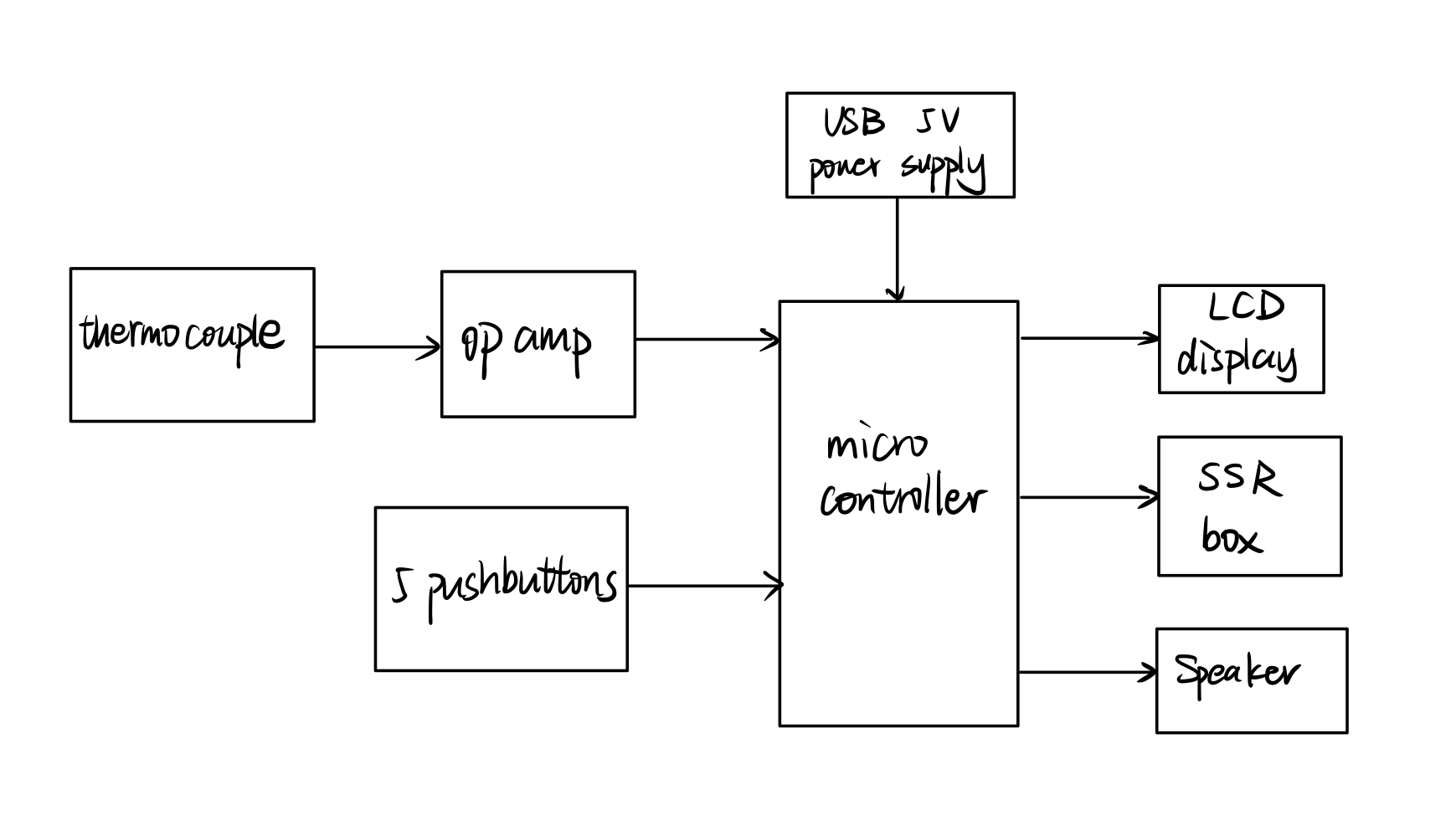
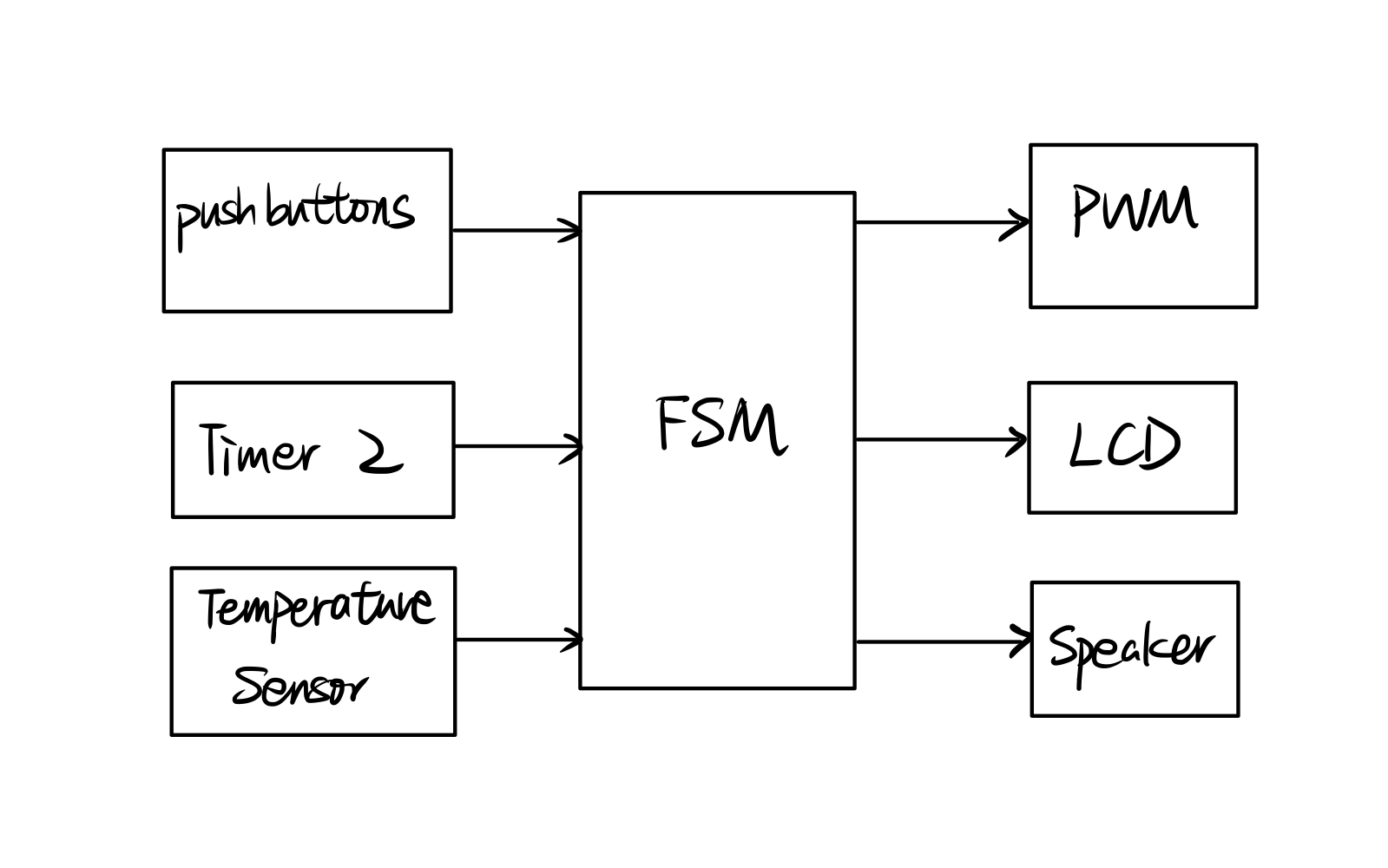
The reflow oven controller integrates temperature sensing, oven power control, and a user interface around the N76E003 microcontroller. A thermocouple and amplification circuit provide temperature feedback, while pushbuttons allow users to configure soak temperature, soak time, reflow temperature, and reflow time. The LCD displays the selected parameters, measured temperature, elapsed time, and current operating state. The software uses a Finite State Machine (FSM) to coordinate the heating and cooling stages, adjusting oven power according to temperature and timing requirements. Timer interrupts support timing and audible notifications, while serial communication sends temperature data to a Python script for visualization. Start/stop control, a heating timeout, and an overtemperature warning support monitoring and operation.
3.Data Synthesis
Our group synthesized data and information to reach appropriate conclusions regarding temperature validation and the functionality of the microcontroller-based reflow oven system.
1. Temperature Validation: Temperature readings from the microcontroller were compared simultaneously with accurate values obtained from a multimeter using Python. The comparison of these two sets of temperature values was conducted in Excel to assess the margin of error ± 3 ℃.
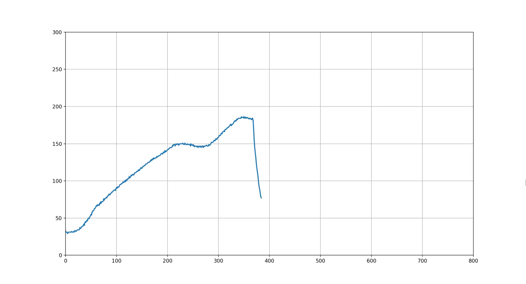
2. Reflow Oven Functionality: The FSM code was uploaded into the microcontroller without any errors to control the reflow oven process. Subsequently, we analyzed the reflow oven graph generated by the Python script. The graph closely matched the expected reflow soldering profile, indicating the proper functioning of the reflow oven system. Additionally, the FSM stages and the temperatures were accurately displayed on the LCD screen.

4.Detailed Hardware Design
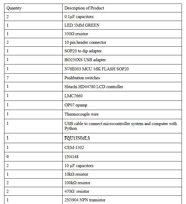
The table below summarises all the parts used for breadboard circuitry for the microcontroller system:
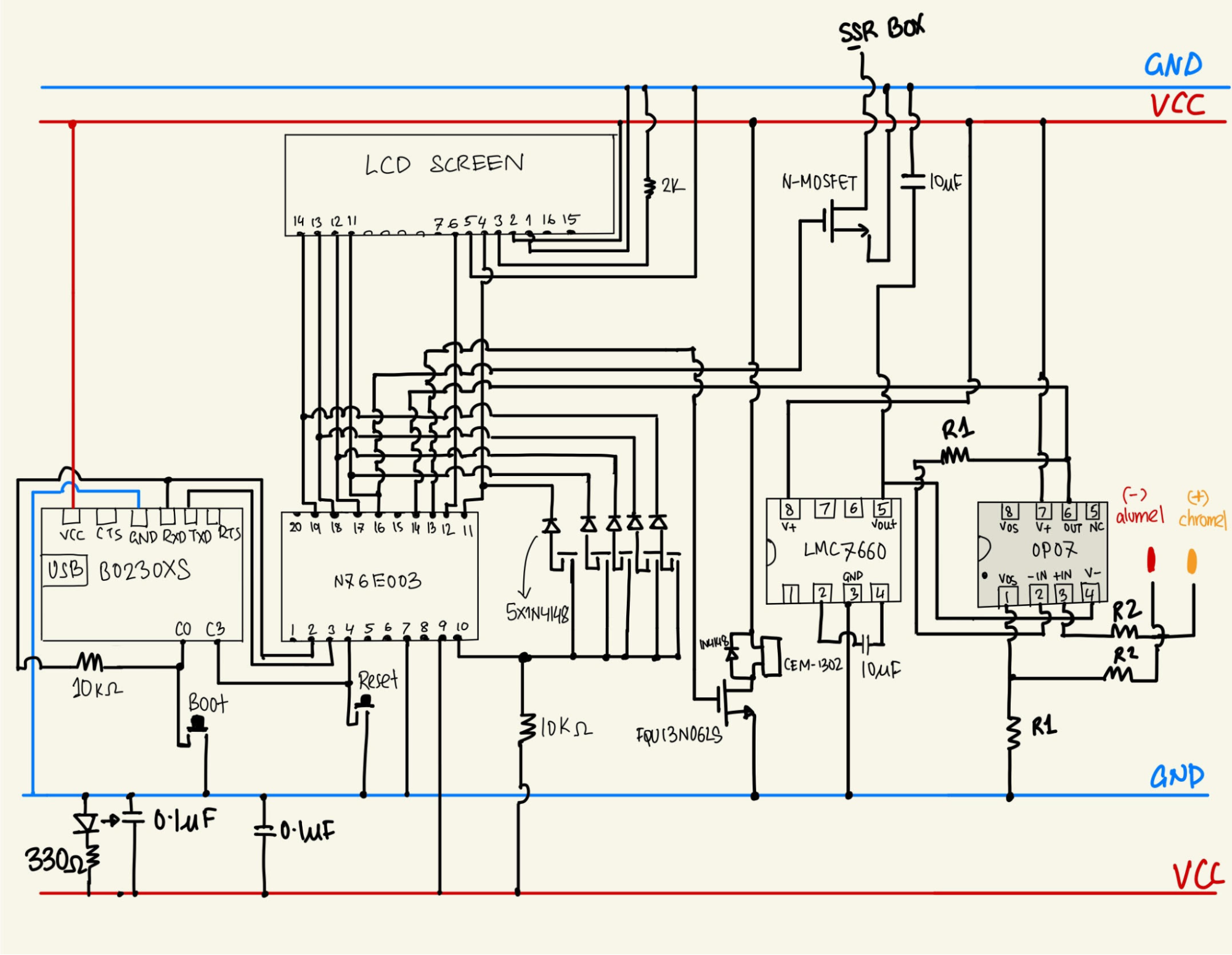
The detailed circuit diagram with all the pinout connections is shown below:
To properly assemble the board and to minimize potential errors, we followed a step-by-step approach:
Making sure the LCD screen works:
i) Connected the BO230XS USB adapter to the N76E003 microcontroller by following the pinout diagram provided by the datasheet [2]
ii) Made sure the microcontroller works by compiling and running test code
iii) Connected the LCM-S01602DTR/M LCD screen to microcontroller system
iv) Wrote and ran sample code (see Appendix B and E) to confirm that LCD screen properly displays
Making sure the buzzer works for the music (extra feature)
i) Attached the CEM-1302 speaker to pin 16 of N76E003. The speaker was connected in parallel to a 1N4148 diode and powered by a FQU13N06LS mosfet.
ii) Tested sample music code before implementing it into the main code to ensure the speaker worked as intended (See Appendix A)
Setting up 5 push buttons
i) Connected 5 1N4148 with 5 pushbuttons and 1 10kΩ resistor to N76E003 and LCD as shown in the above diagram. This was done by putting a diode in series with each pushbutton and multiplexing them by wiring them to the N76E003 and the LCD
ii) Ran sample code (see Appendix C) on the N765003 to confirm that it works
Making sure the correct temperature measurement setup is functional
i) Connected the OP07 opamp to LMC7660 according to datasheet specifications and pinout diagrams [3][4]. The OP07 needs dual power supplies, so LMC7660 delivers both +5V and -5V to the opamp.
ii) Chose appropriate resistor values for R1 and R2 through opamp calculations and repeated trial and error; this is to ensure proper thermocouple voltage amplification.
iii) R1 and R2 resistor values were 100kΩ and 470Ω, respectively.
iv) Made the hot junction of the thermocouple by twisting ends of chromel and alumel of thermocouple and placed it in the oven, and connected the cold junction to the breadboard, as seen in this figure:
v) We recorded the temperature readings in real-time from a temperature range of 25-240℃ and compared them with controller temperatures of Fluke 45 using Python
vi) The temperature differences were within 3℃ range for all readings
Making sure the FSM works on this setup
i) Loaded the main code (see Appendix A) to the N76E003 microcontroller after completing all of the above-mentioned steps
ii) The stages were correctly displayed along with of the extra features and the speaker worked accordingly at the end of the demo
iii) The push buttons were working as expected and we could increment and decrement values with them
5.Detailed Software Design
Variable Initialization
Our team uses 185 lines of code to initialize variables. We allowed the interfacing with hardware by assigning pins for the LCD, speaker, and pushbuttons as well as different strings to be displayed in the LCD. A keyboard was created to initialize the frequencies of notes. We also reserved space for flags, temperature, time, FSM state indicator, etc.
Initialization and Interrupt Service Routine for Timer 0 and 2
Timer 0: After initialization, timer 0 is set to execute every 1/4096Hz to generate a 2048 Hz wave to the assigned pin (SOUND_OUT). The pin is connected to the speaker, which outputs a sound based on the set frequency. Different frequencies were used to generate different sounds.
Timer 2: This timer is used to manage the various counters, such as the power and second counter. The interrupt occurs every 1 ms. The timer 2 function contains a variable that increments every time the interrupt is used and it compares the power percentage desired. If the carry bit is set to 1, it ends the interrupt until the counter equals the power percentage. If the variable counter reaches 100, it increments the second counter.
Push Button Setup
Four push buttons are used to set the soak temperature, soak time, reflow temperature, and reflow time. We created a function that increases the parameter while the button is held. A short delay is applied so that users can press shortly when changing the parameters step by step. Our design does not feature a decrement parameter; instead, we set a threshold for each parameter that automatically loops back to zero when the parameter reaches its maximum value.
We assigned one push button and a flag to the start/stop function. When users push the button, the flag toggles between 1 and 0 to indicate start and stop. After a stop is requested, the FSM state will not change unless the button is pushed again.
Data Transfer through Serial Port and Display with LCD
We used the Display_BCD function to send BCD data to the LCD.
Voltage to Temperature Conversion
We converted voltage output to temperature using functions in math32.inc.
Temperature Comparison Function
The temperature comparison function reads the temperature value and compares it to a value stored in register ‘A’. After using the Display_Data function, it is used to store the temperature value in variable ‘Y’ and then compared with the value of register ‘A’ inside variable ‘X’. Both of these variables are stored in hexadecimal. We then use the x_lteq_y function in the math32.inc file to compare if ‘X’ is lesser than ‘Y’. The ‘mf’ flag is set to 1 if ‘X’ is less than ‘Y’, and 0 if it isn’t.
Main Loop
In the main loop, we display default parameters and enable interrupts for the FSM.
Finite State Machine
State Setting
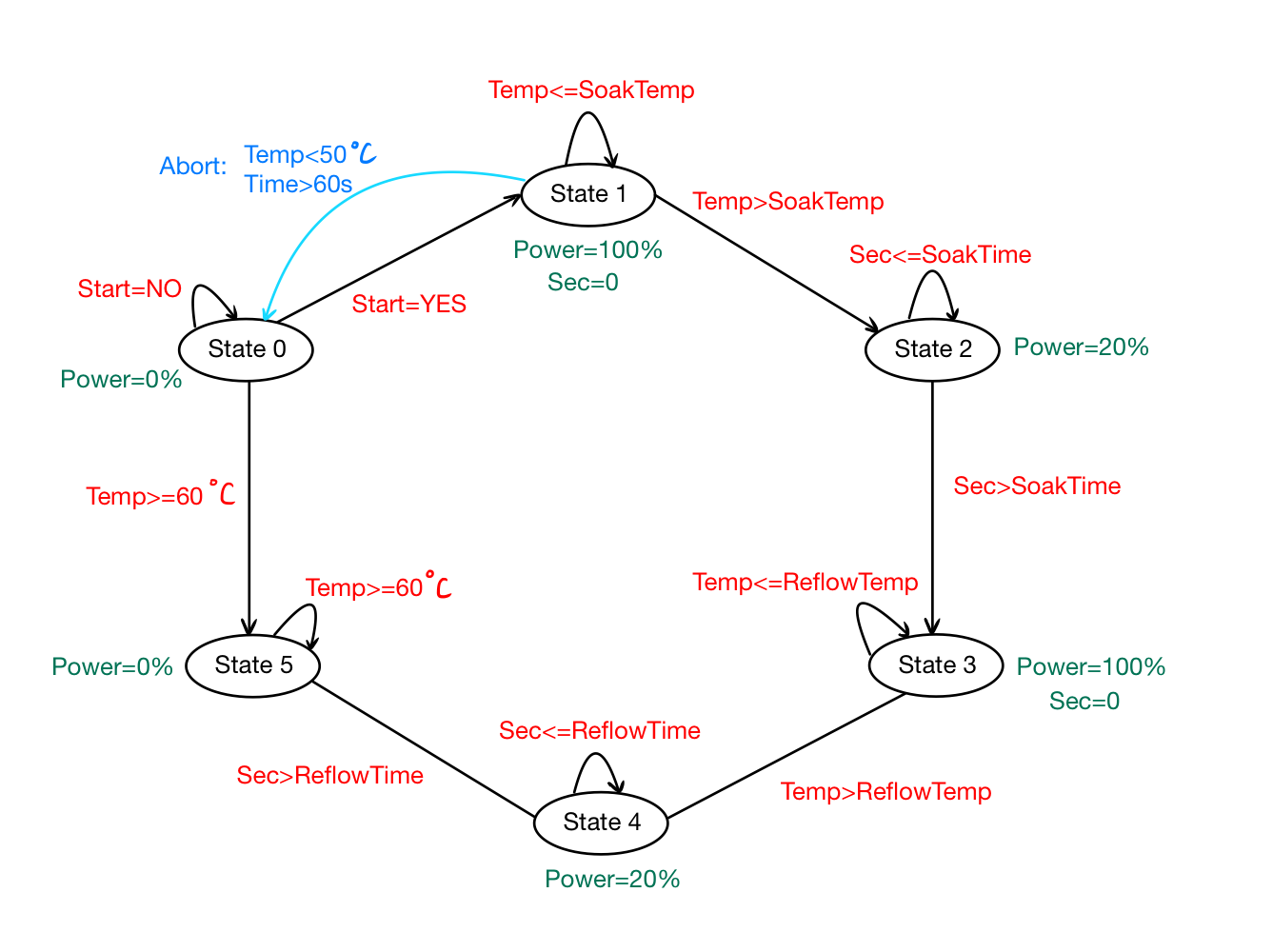
There are six states in total in our finite state machine. The detailed FSM diagram with all states and conditions is shown in the figure below:
Abort
The abort function is called when the temperature inside the oven does not reach 50℃ within the first 60 seconds of starting.
Compare Temperature
Compare the desired temperature constantly in the ramp to reach the desired soak temperature and the ramp to reflow temperature.
Display strings and values
Constant strings are displayed in the LCD to indicate the current state to the user. The temperature values and seconds are displayed as well in each state using the different counters.
PWM
Across different states, we load PWM with a number (0 to 100) that indicates the current percentage of the power in the oven. Loading 0 to the PWM variable at the setting(state 0) and the cooling (state 5) would indicate that the oven should be off. During ramp to soak (state 1) and ramp to peak (state 3), full power should be applied to the oven, so the PWM variable will be changed to 100. During preheating (state 2) and reflow (state 4), only 20 percent of the power is required.
Music
As forementioned, we initialize a keyboard with different frequencies. In state 6 of the FSM, we reload frequencies into Timer 0 and set the proper length of delay to create the melody of Turkish March. Only nine bars of the piece were created since our original intent was to notify users at the end of the cooling stage.
Special Characters
We created special characters using an online custom character creator [1]. It provides an 8x16 bitmap where you can craft your shapes and convert the bits to hex-decimal values. To coordinate with our music, we created a bell, a music note, a double music note, and a bell. Later in the code, we write additional branches to display these special characters.
Overheat
If the temperature of the oven exceeds 250 ℃, the LCD will indicate "too hot," alerting the user to an abnormal oven condition. Our team creates a fire character, which shows on the LCD as well.
6.Conclusion
Our team designed a reflow oven controller using the N76E003 microcontroller. The purpose of the oven controller is to assemble surface mount devices (SMD) onto PCBs by carefully heating the solder paste. The software was written in 8051 Assembly. The controller can measure temperatures ranging from 25℃ to 240℃ using a K-type thermocouple. For the user interface, we made sure that the LCD displayed the soak temperature, soak time, reflow temperature, and reflow time. The 5 push buttons are used to select the parameters, start and stop the reflow process, and reset the oven. As a safety precaution, the reflow process is aborted if the oven does not reach 50℃ in the first 60 seconds.
In terms of problems, we had the most trouble calculating the R1 and R2 resistor values to obtain the optimal gain value for the opamp. The hardware team needed to validate the controller temperature data using the lab multimeter multiple times due to issues with the testing procedure; these issues were eventually fixed, but it still took a significant amount of time. For the software team, debugging the main code was a huge obstacle due to the many stages and flags of the FSM. Furthermore, the extra features needed to be integrated with the main code, and then debugged. Despite the challenges, our team took around 35 hours of hard work to complete the project and create a functional reflow oven controller.