Embedded System · 2024
Metal Detector Rover
A wireless metal detector robot capable of reporting magnetic field strength.
1.Overview
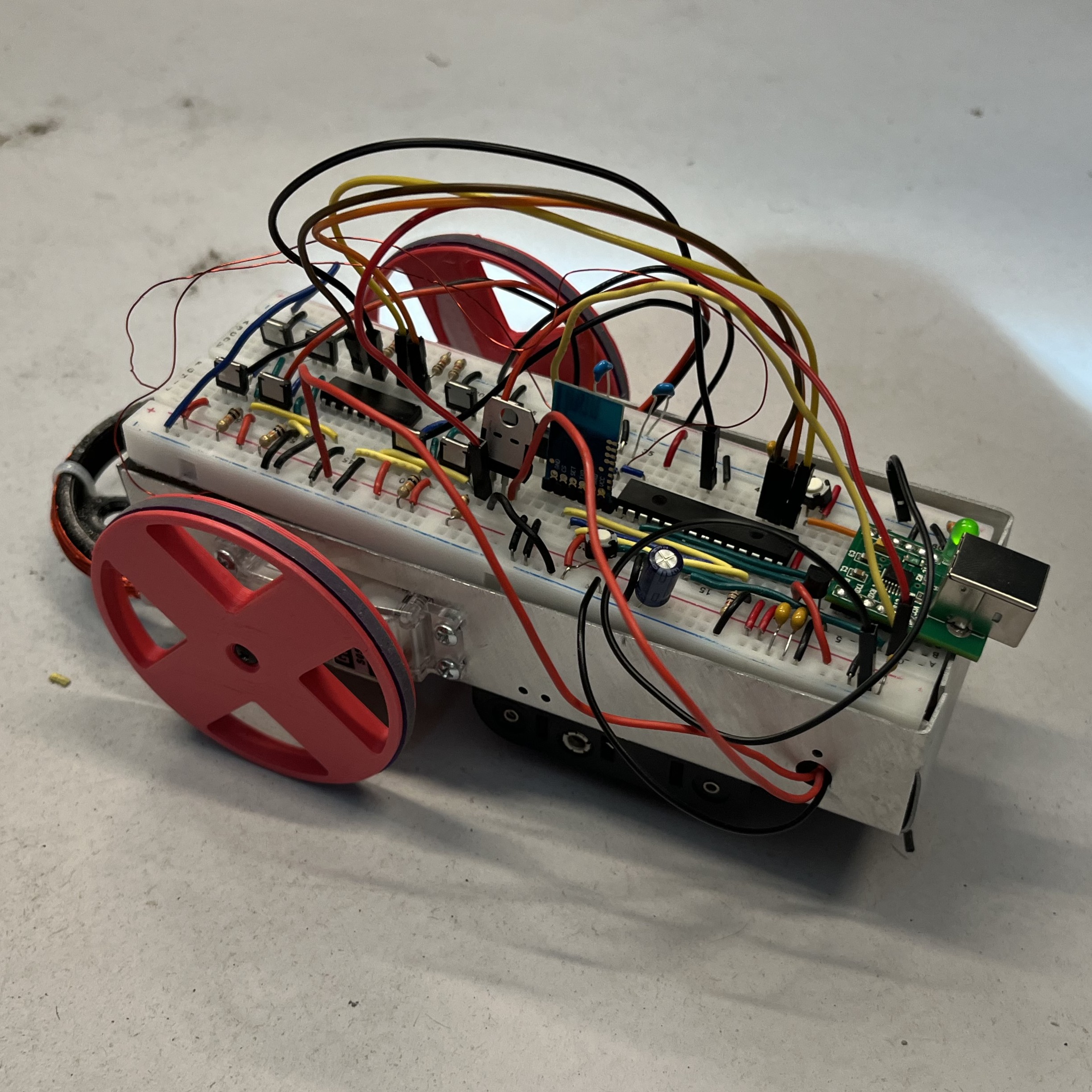
This project aims to design and build a remote-controlled metal detector robot. This robot and remote must use two microcontrollers from two different families and use the JDY-40 to establish radio communication. Both the remote and the robot are battery-powered. The DC motors on the robot utilize MOSFETs and optocouplers for control, and the motor should be calibrated so that the robot would avoid drifting left or right when going forward. The robot must be able to detect any kind of metal using an inductor. A buzzer is attached to indicate the detection of metal along with the signal intensity. The strength of the signal is then displayed on an LCD screen attached to the remote controller. The robot should be able to maneuver smoothly and demonstrate complex driving patterns such as figure-eight, square, and “I”. Both the speed and direction should be adjustable.
2.System Architecture
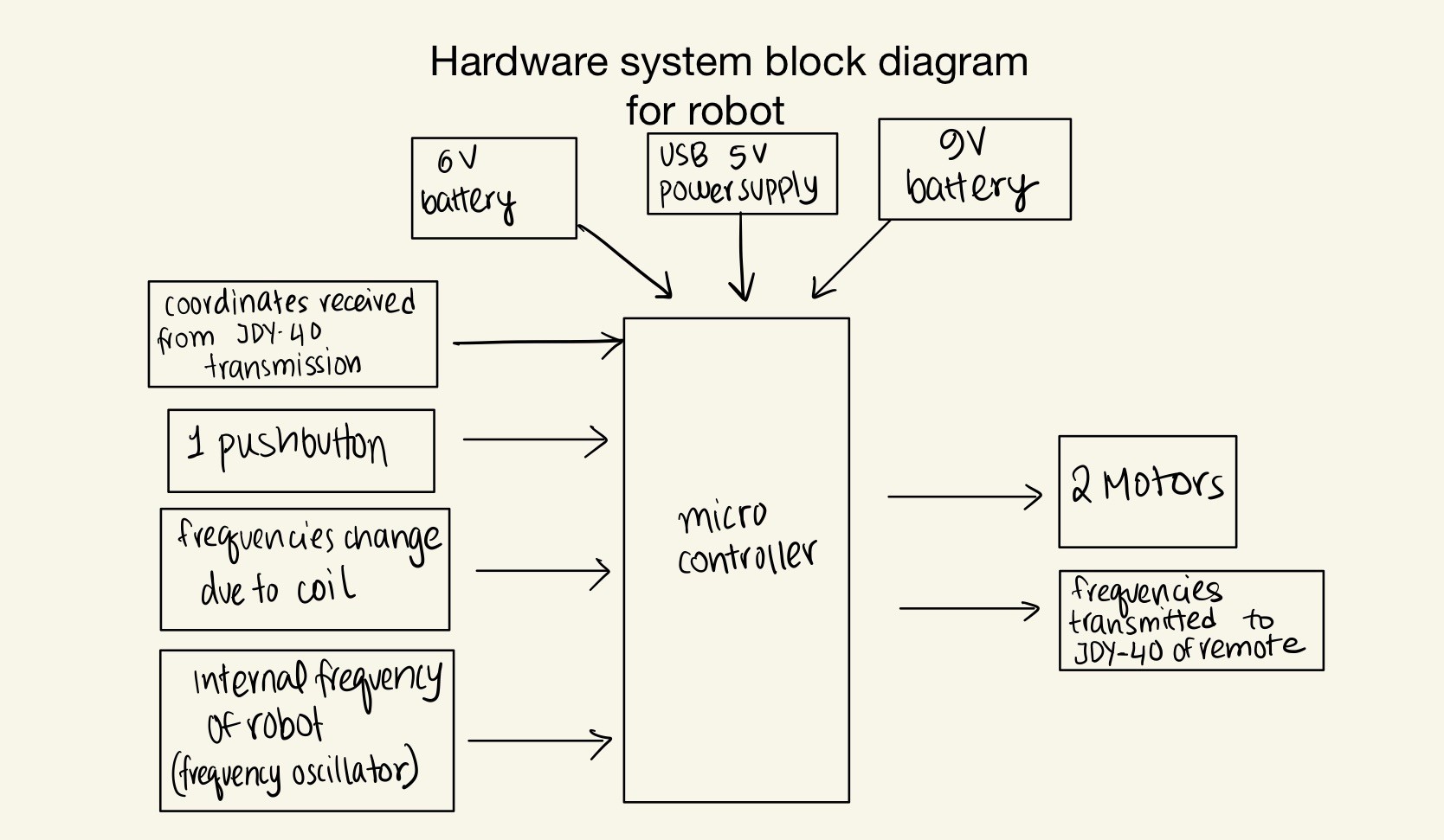
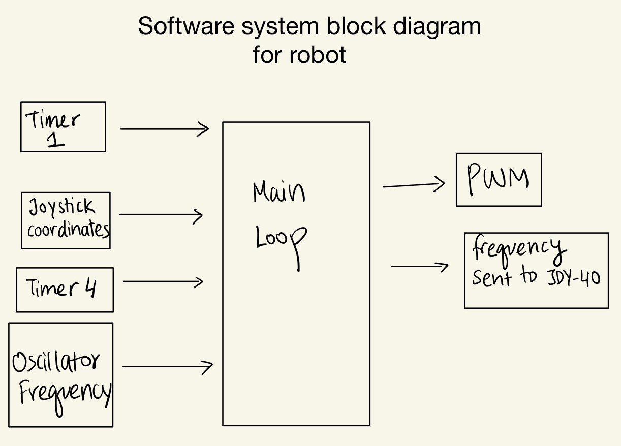
The system consists of a PIC32-based robot and an EFM8-based remote controller connected through a pair of JDY-40 radio modules. The remote reads joystick coordinates through an ADC and initiates communication to send movement commands and request metal detection data. On the robot, the PIC32 converts these commands into timer-driven PWM signals that control two DC motors through H-bridge circuits. It also measures changes in the Colpitts oscillator’s frequency relative to a calibrated baseline, converts them into metal detection intensity levels, and transmits the results to the remote. The remote displays the intensity on an LCD and adjusts the buzzer frequency to provide audible feedback. A second EFM8 handles recorded voice playback, reading audio from 25Q32 flash memory and outputting it through a DAC and LM386 amplifier to the speaker. Battery supplies and voltage regulators power the motor, control, and communication circuitry.
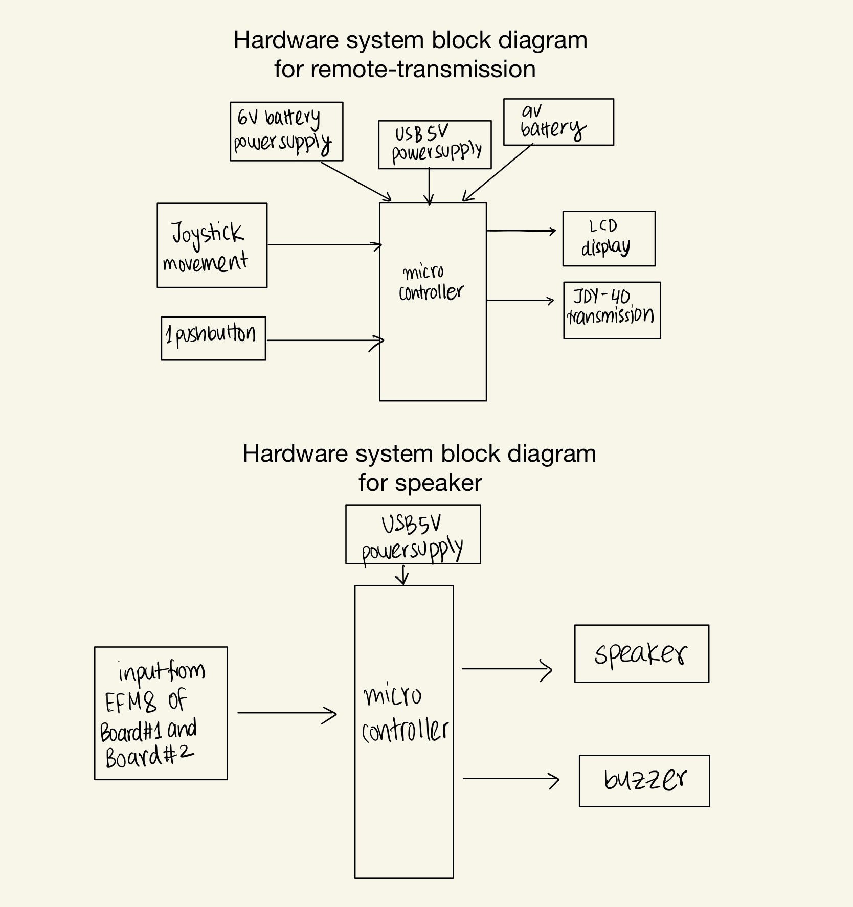
3.Detailed Hardware Design - Robot
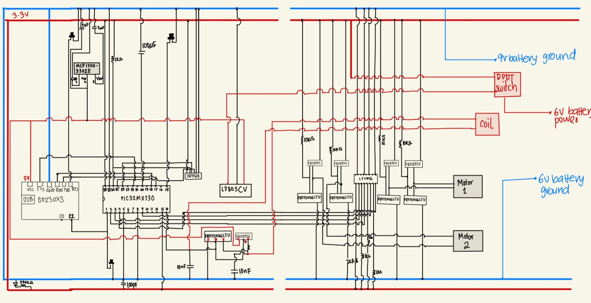
The hardware design is responsible for the transmitter signal, motor control, and the oscillator. The main breadboard, battery pack, ball caster, and DC motors are housed in a pre-made aluminum chassis. One 9V battery and four 1.5V batteries are used to power the robot. The following sections describe the main hardware components of the robot in detail:
Voltage Regulator (3.3V and 5V): The L7805CV voltage regulator converted the 9V battery into 5V, for powering the BO230XS USB receiver. The 5V is then converted into 3.3V by another regulator (MCP1700) to power the JDY-40 and the PIC32.
PIC32 Microcontroller and JDY-40: The PIC32 is the main microcontroller of the robot. The JDY-40 is used by the PIC32 to send and receive strings.
H-bridge: The H-Bridge allows the motors to be able to spin in one direction, while also being able to reverse its direction depending on the pins connecting on the optocoupler. The H-Bridge is composed of optocouplers, two 1 kilo-ohm resistors, two 10 kilo-ohm resistors, two n-channel MOSFET, and two p-channel MOSFETs.
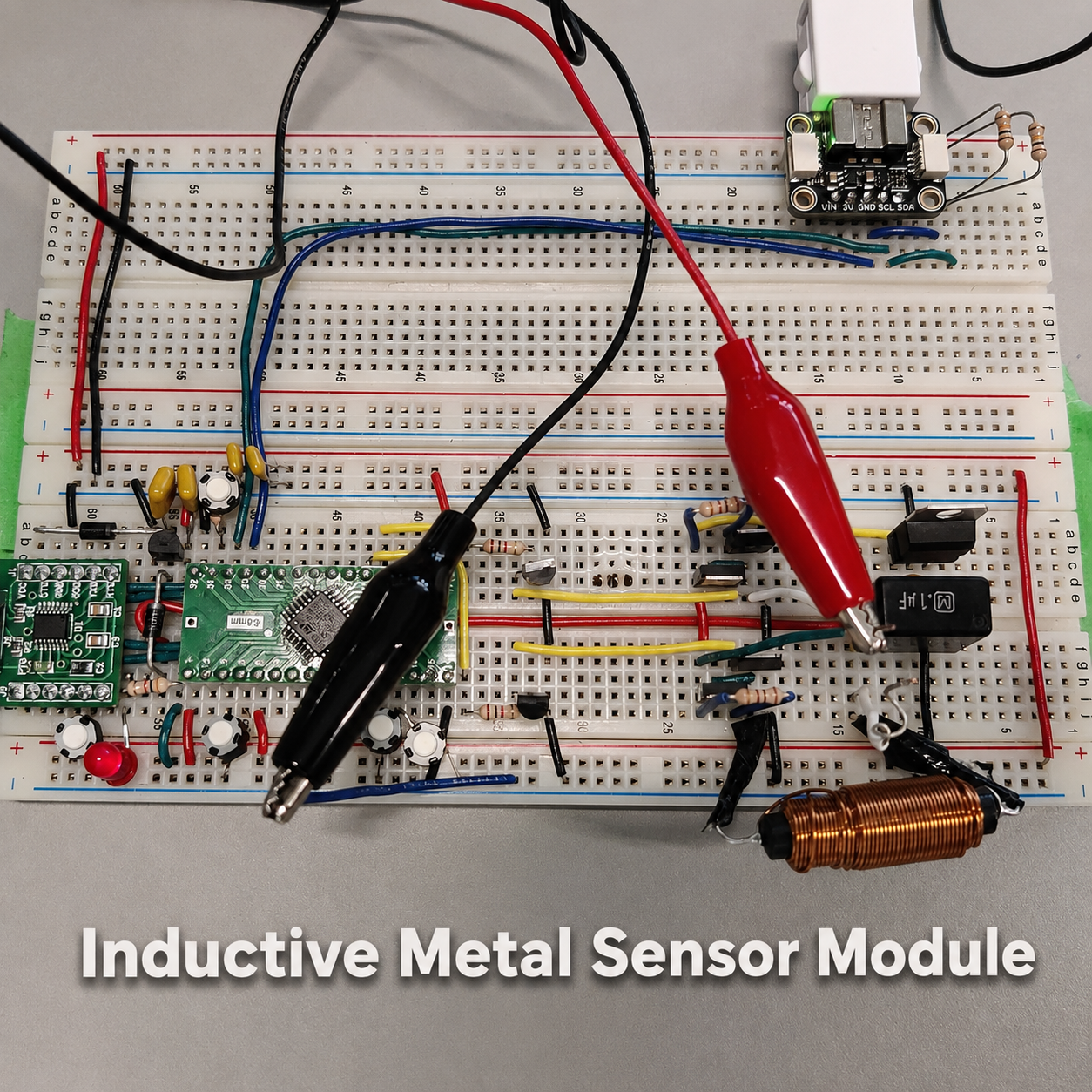
Colpitts Oscillator: This circuit consists of two capacitors, a resistor, an inductor, and a CMOS inverter. The CMOS inverter is made up of one p-channel and one n-channel MOSFET. The frequency of the inductor changes when metal gets close to the coil. This frequency is measured by connecting the gate of one of the MOSFETs to an ADC pin on the PIC32.
The detailed schematic of the pinout diagram for the robot is shown below:
4.Detailed Hardware Design - Remote
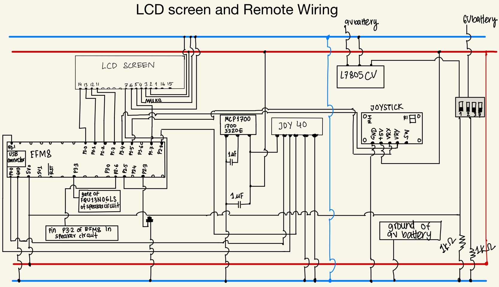
The remote design is mainly responsible for the functions of five components: transmission, the joystick, the LCD, the buzzer, and the speaker. In total, four breadboards, and two EFM8 microcontrollers were used to assemble the remote circuit. We apply three 1.5V batteries in series to supply a sum of 4.5V to the speaker and one 9V battery for the other components. The following sections include detailed descriptions for each of them:
Board #1: Board #1 and Board #2 share one EFM8 microcontroller and the same software design. We used board #1 for the LCD only.
Board #2: Transmission, the Buzzer, and the Joystick. Our team used a pair of JDY-40s that receive and send messages between the remote and the robot. A buzzer is connected to a pin of the microcontroller which increases the frequency when the strength of the metal increases. A joystick, which acts as a potentiometer, sends different voltage signals to the board when the positions of the x and y-axis values change.
The detailed circuit diagram with all the pinout connections in board #1 and board #2 is shown below:
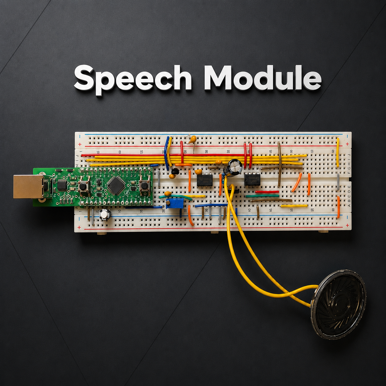
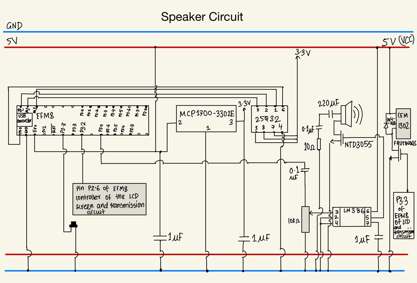
Board #3: The Speaker. This board includes another EFM8. The two microcontrollers are connected by one pin from each, thus the message “metal detected” is triggered when a voltage signal is sent from the main transmission EFM8. The two main chips included on this board were 25Q32 and LM386. The former stored the flash memory of a WAV file, and the latter amplified the sound.
The following diagram illustrates the connections for the speaker:
Board #4: Battery Holder. This board holds three 1.5V batteries and a 9V battery.
5.Detailed Software Design - Robot (Receiver)
The robot is responsible for sending metal intensity values to the remote and receiving commands to execute specific movements. The robot acts as the slave; it only receives and transmits strings when the master (the remote) sends it a ‘M’. The following sections detail how the robot functions.
Variable Initialization
To start, we defined constant values such as system clock, baud rate, and max voltage for the joystick. We then initialized volatile int variables to control the PWM: ISR_pwm1, ISR_pwm2, and ISR_cnt. In the main loop, we defined int counters for both the timeout counter and the JDY-40 (timeout_cnt, cnt), an array to hold the PWM values of each wheel (pwm_arr), and the variables that would be received and sent using the JDY-40 (buff[ ], holder[ ]), and int values for frequency (f), and x and y (x,y).
Timer 1 and 4 Initialization and Interrupt Service Routine for PWM
Timer 1/PWM ISR: After initialization, timer 1 is used in the PWM ISR. The timer generates square waves for either wheel depending on the value of ISR_pwm1 and ISR_pwm2. The ISR_cnt is a time counter that would increment every 10 us. It is set back to zero upon 10000 or every 100 ms. The ISR_pwm can be set from -10000 to 10000 to determine the direction and speed of the motor. If the ISR_pwm is negative, the motors spin backward, if they are positive, the motors spin forward. If ISR_pwm is zero or ISR_cnt reaches the desired ISR_pwm value, the motor turns off. Timer 4 waits for a set amount of microseconds.
JDY-40 Functions
Two primary functions, SerialRecieve and SerialTransmit were used in transmission. SerialRecieve receives a string and copies it into a local buffer string. SerialTransmit would copy a local buffer string and send it to the other JDY-40.
Sprintf Alternative
To improve the performance of the main loop, we made a faster version of sprintf that would convert integer numbers to strings. This was done using integer division and the modulo operator. This function was used in both the receiver and transmitter code.
PWM Value Calculation
We created a function named pwmcalc to calculate the PWM values that would be sent to the ISR. The PWM value consisted of a magnitude and direction. The direction was calculated by setting each wheel to 0%, 50%, or 100% depending on the x and y values given by the joystick. For instance, if the joystick was moved to the top left corner, the right wheel would be set to 100% and the left would be set to 50%, to turn left.
The magnitude is represented as a ratio; it is the square root of the normal of x and y squared divided by the max voltage of the joystick. The PWM values are calculated by multiplying the magnitude and direction.
Metal Detection Function
The function LevelSender was used to detect metal. The default metal frequency was set by measuring the frequency of the oscillator without any metal nearby; this is automatically done whenever the robot is reset. In the main loop, the robot would continuously record frequency values. LevelSender would subtract that value with the default frequency to determine the intensity of nearby metal.
The intensity of the metal detector is divided into 4 levels: level 0, 1, 2, and 3. Level 0 means there is no metal nearby, and level 3 means that there is a lot of metal nearby.
Main Loop
The main loop is comprised of two parts: an if statement for sending/receiving strings, and the PWM calculation. A signal is received when the JDY-40 sets the URXDA bit to ‘1’. When this happens, the SerialRecieve function is called, and the received string is checked; if it contains an ‘M’, then the message is let through. Afterward, the length of the message is checked. If the string fails either of these checks, it is discarded. After those checks, the string is decoded and its contents are assigned to an integer for x or y. This is done using the atoi function.
Now the receiver must send metal intensity to the transmitter. First, the current frequency is calculated using the GetPeriod function. LevelSender is then called and returns the metal intensity. This metal intensity is then put into a buffer string using our modified sprintf, and sent to the transmitter using SerialTransmit.
Finally, the PWM values for each wheel are calculated by calling the pwmcalc function. At this point, the loop resets back to the beginning.
6.Detailed Software Design - Remote (Transmitter)
The software design for the remote controller was written in C. The remote acted as the master of the transmission process. It sends the letter “M” as an instruction for the robot to send any string. The code is responsible for the functionality of the buzzer, the transmitter, and the joystick. The following sections describe how we implemented these.
Variable and Timer Initialization
At the start of the code, necessary constants for the timer like baud rate were defined. The pinout connections between the microcontroller and the rest of the hardware components were also listed. Next, we initialized timers 2 and 3 and their respective ISRs. Timer 3 was used for the Timer3us function and waitms which waits for a set number of milliseconds. Timer 2 was used to output a square wave to the buzzer.
LCD Functions
Two LCD functions initialized the LCD screens' pins and displayed the metal's strength. The remote received the level of intensity from the robot. The string would then be displayed on the LCD with a short delay to ensure readability.
Voltage Reading Functions
The joystick works as a potentiometer. It outputs a voltage to indicate the position of the stick. The joystick was given a 4.8V, and the middle position resulted in a 2.4 V in both the x and y axes. The top right corner position would result in a 4.8V in x and 4.8V in y, while the bottom left would give (0,0) in x-y coordinate. Therefore, reading the voltage output of the joystick was essential. To do this, we initialized an analog-to-digital converter (ADC) and used it to measure the voltage of the pins.
Main
In the main function, we first called the initialization functions. The voltages of the x-axis and the y-axis were read through ADC and sent using thefastestsprintf function. The buzzer reload was included in the main function, too. Since the robot sent a metal intensity between 0-3, we simply multiplied that value by 200 to calculate a frequency. The frequency of the buzzer is raised by 200Hz as the robot approaches the metal.
Speaker
Unlike any other remote components, the speaker was connected to another EFM8 and used a different code. The speaker program was divided into two parts: one was to load the WAV file into 25Q32, which has 32Mb of memory, and another was used to trigger sound out once a button was pressed. We used an online website to generate a speech file, converted it into a WAV audio file, and then loaded it into flash memory using the sample code. The other part only contained the logic to trigger the button. To do this, we used a digital-to-analog converter (DAC). It was used to read the memory of the chip and output the voltage required. Since there was a wire connected between two EFM8s microcontrollers, we created a pulse in the main function which acted as a button to trigger the sound
7.Conclusion
The objective of this project is to design and construct a remote-controlled metal detector robot. The remote controller and robot were constructed using microcontrollers from two distinct families, with communication facilitated by the JDY-40 radio module. The robot can detect the metal and report the strength of the metal signal and display with an LCD screen and a buzzer that changes frequency. A speaker is attached for a user to play customized messages. Lastly, the robot can move in fundamental directions and perform intricate driving patterns, including figure-eight, square, and straight paths.
We mainly spent time for troubleshooting We had delay and noises for the radio transmission. We resolved this issue by checking the hardware component, transmitting data with smaller size, and relocating to an environment with less signal interference. The main problems we encountered were having delay and noises for the radio transmission. Overall, our group spent approximately 50 hours completing this project.