Robotics · 2025
Autonomous Self-Balancing Robot
A two-wheeled self-balancing robot integrating feedback control, Bluetooth remote operation, and live video with object detection.
1.Overview
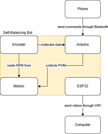
outlines the development of a two-wheeled self-balancing robot designed to maintain an upright position while being remotely controlled via Bluetooth.The system is based on the Arduino Nano 33 BLE Sense Rev2, using onboard IMU data and a PID controller for real - time balancing.Speed feedback is provided by AS5600 rotary encoders, managed through a TCA9548A I²C multiplexer.An ESP32- CAM module enables video streaming and object detection using OpenCV.The project integrates control, communication, and vision systems, demonstrating practical applications of embedded systems and feedback control.
2.Description of Final Design
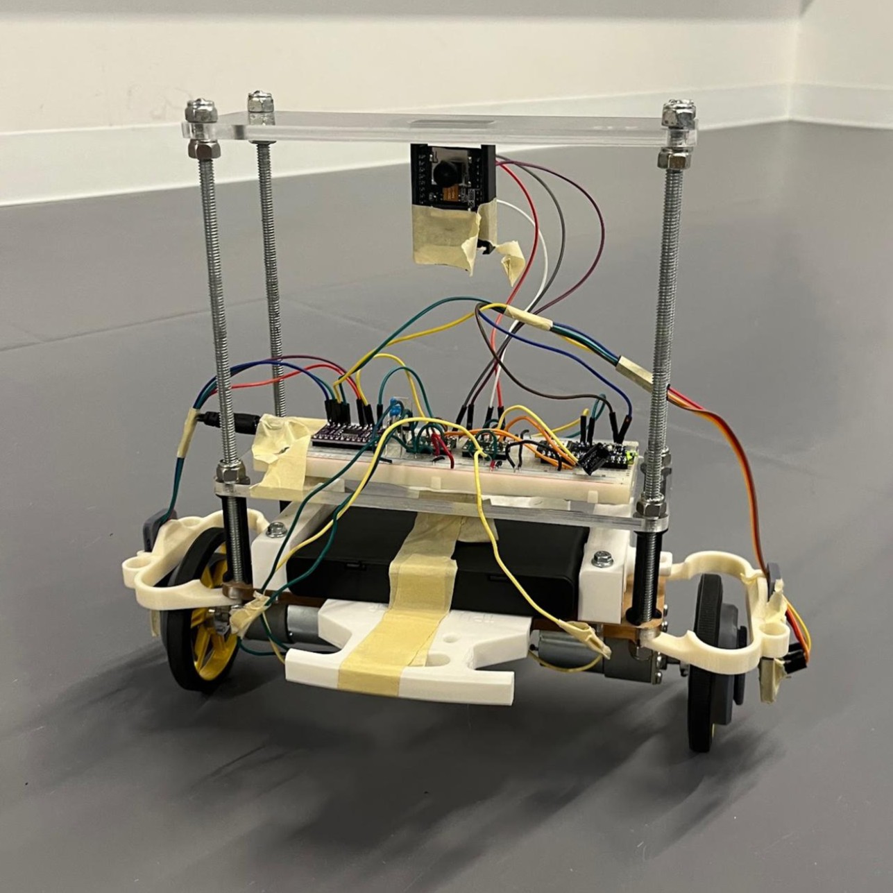
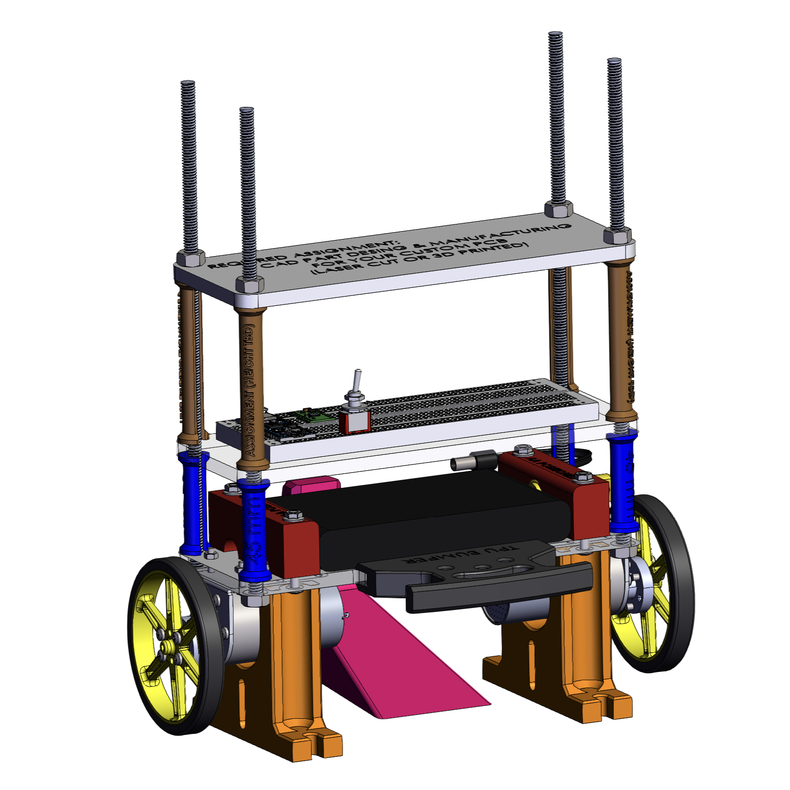
The robot’s main structure consists of three vertically stacked plates. The bottom plate holds the battery pack on top and supports two motors mounted on either side. The middle plate houses the breadboard, which serves as the central hub for most electrical connections. The top plate is positioned at the highest level, primarily to aid in balancing and to serve as a mounting point for the camera. Four metal rods run through the corners of the plates, providing alignment and structural stability to the overall assembly.
The robot is controlled using an Arduino Nano 33 BLE Sense Rev2. It generates Pulse Width Modulation (PWM) signals that are sent to two motor driver PCBs to independently control the left and right motors. The Arduino’s built-in Inertial Measurement Unit (IMU) is used to measure the tilt angle of the robot relative to the vertical axis. These tilt readings are processed by an angle PID controller, which adjusts the motor PWM signals to counteract any imbalance and keep the robot upright.
However, the angle PID controller alone is not sufficient for stable self-balancing. To improve stability, we also implemented a speed PID controller using one encoder. The encoder measures the rotational speed (RPM) of the left wheel. The speed PID controller uses this data to determine the appropriate PWM adjustments needed to maintain the desired motion and stability.
An additional feature of the robot is a camera module mounted on the top plate. An ESP32-CAM is used for basic object detection. The object detection firmware is flashed onto the ESP32 before it is connected to power. The module is powered through connections to the breadboard via jumper wires.
3.System Design
The self-balancing robot consists of three core subsystems: electrical, mechanical, and software. Each subsystem plays a crucial role in achieving stability, responsiveness, and additional features such as wireless control and object detection. This section details the hardware components used for sensing, actuation, and power management, the mechanical structure enabling physical stability, and the modular coding framework that integrates control logic, communication, and vision processing.
4.Electrical Subsystem
The electrical subsystem integrates all key components responsible for sensing, processing, actuation, and power distribution. It enables real-time control of the robot's balance and movement through a coordinated interaction of sensors, microcontrollers, drivers, and power electronics.
Microcontroller: Arduino Nano 33 BLE Sense Rev2
Powered by a regulated 5V supply from the 12V battery pack through a step-down voltage regulator. Handles sensor readings, motor control signals, Bluetooth communication, and overall system logic.
Motor Drivers: Two DRV8833 Dual H-Bridge modules
Receive PWM signals from the Arduino to control the speed and direction of the DC motors. Connected directly to the battery pack (12V) to power the motors.
Motors: Two Pololu 4741 DC motors
Provide torque and speed for balancing and maneuvering. Directly controlled by the DRV8833 motor drivers.
Encoders: Two AS5600 Magnetic Rotary Encoders
Measure the angular velocity of each wheel to support velocity feedback and control. Connected via I²C interface through a multiplexer due to identical I²C addresses.
Multiplexer: TCA9548A I²C Multiplexer
Allows communication with both AS5600 encoders by enabling one I²C channel at a time. Controlled by the Arduino to switch between encoder channels dynamically.
Voltage Regulator: 5V Step-Down Regulator
Converts the 12V battery pack voltage to a stable 5V for powering the Arduino and other low-voltage components.
Power Supply: Rechargeable 12V Battery Pack
Provides the main power source for the motors and motor drivers, and regulated 5V supply for logic-level components.
5.Mechanical Subsystem
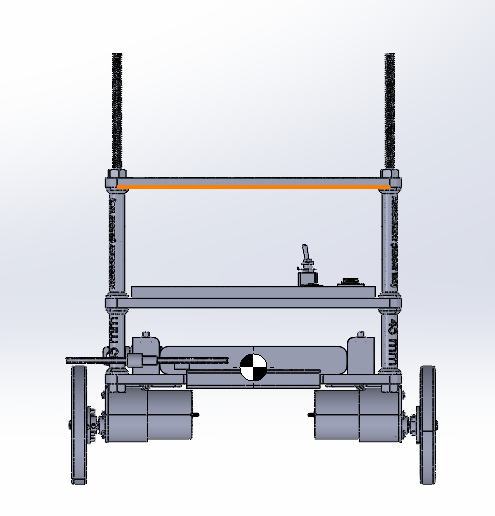
The mechanical subsystem provides the physical framework that supports all electrical components while ensuring the robot's center of mass is optimized for balance and stability during motion.
Overall, The robot is built from three vertically stacked plates supported by four metal rods at the corners. This modular structure securely houses the Arduino, motor drivers, battery, and other components, while maintaining structural rigidity and a clean layout. The vertical stacking also helps elevate key components such as the camera for an unobstructed field of view.
Motor Mounts and Wheels:
Motors securely mounted to chassis, with wheels properly aligned to ensure smooth movement and accurate balancing control.
Sensor Placement:
Arduino (with integrated IMU sensors) is securely mounted to detect precise orientation and motion accurately.
Battery Housing:
Strategically positioned to maintain a low center of gravity and enhance stability.
Camera Module Mounting (ESP32-CAM or similar):
Securely mounted to provide an unobstructed view for real-time video streaming and object detection tasks.
6.Software Subsystem
The code is modular and organized into distinct components for motor control, sensor processing, Bluetooth communication, video streaming, and object detection. It is primarily written in C++ (Arduino IDE) for real-time control and Python for external processing tasks such as object detection.
1. Main Control Loop (Arduino Nano 33 BLE Sense)
Implements a dual-loop control system: An angle PD controller maintains balance using tilt data from the BMI270 IMU. A speed PI controller adjusts motor speed using real-time RPM feedback from AS5600 encoders. A complementary filter is used to fuse sensor data and act as a weighting factor between the angle and speed controllers. The combined output of this system feeds into a final PID controller, which generates the PWM signals used to drive the motors.
The main loop continuously reads sensor data (angle and RPM), filters and computes PID outputs, and sends PWM values to the motors for stable balancing and maneuvering.
2. Encoder and Multiplexer Handling
To handle the identical I²C addresses of the two AS5600 magnetic encoders, the system uses a TCA9548A I²C multiplexer. This allows the Arduino to communicate with one encoder at a time by dynamically opening and closing specific I²C channels. The RPM data from each encoder is read in turn and used for speed feedback in the control loop.
3. Motor Control Module
Motor control is based on PWM signals generated from the outputs of the PID controllers. The system supports multiple driving modes including forward, backward, slow decay, and differential turning. These behaviors are implemented through modular functions defined in a dedicated movement.h file, allowing clean and reusable control logic.
4. Bluetooth Communication
The ArduinoBLE library enables real-time Bluetooth communication with a mobile app. Commands such as W, A, S, D, and 0 are used to control movement directions and stopping. These inputs are interpreted as setpoints and passed to both the angle and speed PID controllers, enabling responsive remote control.
5. Video Streaming (ESP32-CAM)
An ESP32-CAM module is used for video streaming, running a web server that broadcasts MJPEG video at a resolution of 320×240. The live video stream is accessible through the module’s IP address, providing visual feedback to the user for remote navigation and monitoring.
6. Object Detection & Email Alerts (Python)
A Python script uses OpenCV along with a pre-trained SSD MobileNet model for object detection in the ESP32-CAM video stream. Detected objects are annotated and displayed in real time. The system also allows the user to send captured frames via email and change the recipient address. A custom file is used to load a list of 91 object classes for detection.
7. Parameter Tuning Interface
For tuning the PID controllers, the system includes a serial-based interface that allows dynamic adjustment of control parameters such as Kp, Ki, and Kd. Commands like "kp", "ki", "s", and "reset" can be entered during runtime to fine-tune system behaviour and improve balancing performance during testing.
7.Discussion
In this project, we successfully built a self-balancing robot capable of maintaining its upright position by reading the tilt angle using a gyroscope and accelerometer and measuring motor speed with encoders. These sensor readings were used to determine appropriate PWM signals to counteract any imbalance, enabling the robot to balance itself in real time.
We also developed a Bluetooth-based remote control app that allowed us to maneuver the robot while it sustained its self-balancing function. Additionally, the robot was equipped with an ESP32-CAM module for live video feedback, and we implemented an object recognition feature using OpenCV.
As a significant portion of the project focused on balancing the robot, we gained valuable hands-on experience with tuning PID controllers. We learned how to intuitively adjust the PID parameters by analyzing the robot’s response and behaviour in real time. This process deepened our understanding of control systems and real-time embedded programming.
8.Recommendation and Future Improvement
One key thing we could improve on is the maneuvering smoothness. Currently, the robot struggles with smooth forward and backward movement due to the balancing mechanism. Future iterations should refine the control algorithm to reduce swaying and enhance responsiveness.
Having a more robust balancing system would lead to better stability and allow for more dynamic movement. This could probably be done through improving sensor fusion or a better-tuned PID loop.
In addition to improving the core functionality, future work could expand the robot’s extra features by adding autonomous navigation, obstacle avoidance, or more advanced computer vision capabilities to make the robot more intelligent and interactive.