Embedded System · 2024
Cardio Health Monitor
A real-time cardio health monitor with live heart rate visualization on an oscillocscope and LCD-based health feedback.
1.Overview
This project explores an embedded heart-rate monitoring system that combines a photoplethysmography (PPG) sensor with a microcontroller and a character LCD. The prototype brings together pulse sensing, timing, and local feedback, with a serial connection providing additional measurement information during development.
The firmware in the repository targets the STM32L051 and is written in C. Its measurement routine determines the interval between successive pulse edges and converts that interval into beats per minute. The interface also introduces prompts for user information, although this part of the published source remains incomplete.
2.System Architecture
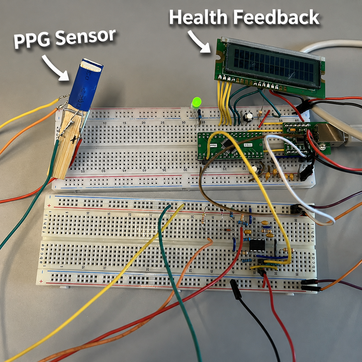
The system follows a signal path from the PPG sensor assembly to a digital pulse input, then to the microcontroller's timing routine and display outputs. The firmware expects a pulse signal on PA8; it measures digital transitions rather than sampling the raw optical waveform with an ADC. The external sensing circuitry must therefore provide a signal suitable for this input.
The STM32 firmware uses a 32 MHz clock and the 24-bit SysTick counter for period measurement and timing delays. A 16-character, two-line LCD connects through a four-bit parallel interface on PA0–PA5, while USART1 provides a serial connection for user input and diagnostic output. The build configuration opens the serial terminal at 115200 baud.
3.Detailed Design
Pulse-period measurement: The measurement routine first synchronizes with the input by waiting for a low level followed by a rising edge. It then counts elapsed clock cycles until the next rising edge. A software overflow counter extends the range of the SysTick timer, allowing the routine to track intervals longer than a single counter cycle. If the overflow limit is exceeded while waiting for transitions, the routine returns a zero result to indicate an unsuccessful measurement.
Heart-rate calculation: The measurement loop requests one pulse period at a time. It converts the accumulated count into seconds using the configured clock frequency, then calculates beats per minute from that period. The result is formatted to two decimal places for the LCD, while the serial output also reports the measured period and counter value. A 200 ms delay follows each iteration; the total update interval additionally includes the time spent waiting for pulse edges.
LCD interface: A separate display module handles initialization, commands, and text output. Each byte is transmitted as two four-bit transfers, reducing the number of data pins required. Its printing function selects either display line and can clear unused character positions, preventing remnants of a longer previous message from remaining on screen.
User interaction: At startup, the display flashes a welcome message and prompts for sex and age, with responses entered through the serial terminal. In the published source, the sex response is not assigned to the variable that enables monitoring, and the age input is not correctly converted from text to an integer. These issues must be corrected before the existing startup flow can reach the measurement loop. The source does not implement a completed health classification algorithm.
4.Deployment
The supplied build configuration uses the GNU Arm Embedded toolchain for a Cortex-M0 target. It compiles the application and LCD driver alongside startup, serial, and system support modules, links the firmware with an STM32L051 linker script, and produces an Intel HEX file. The programming target uses stm32flash and launches a PuTTY serial terminal afterward.
Rebuilding the project requires the shared headers, source files, and linker script referenced through the adjacent Common directory, as well as the programming utilities referenced by the build file. After correcting the startup input handling, verification should begin with a known pulse signal on PA8 to check the period and BPM calculation, followed by testing with the sensor assembly. When the measurement routine times out, the existing code reports NO SIGNAL through the serial terminal.
5.Conclusion
The project brings together pulse timing, embedded C, LCD control, and serial communication in a compact heart-rate monitoring prototype. Its central design translates the timing of a digital pulse signal into a readable BPM value, while separating display handling from the main measurement logic.
The next development steps are to complete and validate the startup input handling, add filtering across successive readings, and provide a clear signal-loss message on the LCD. These improvements would make the prototype more consistent and easier to use while building on the existing sensing and display architecture.